Everything Old Is New Again – December 6, 2019

The Wright Brothers After Kitty Hawk – November 29, 2019
November 30, 2019
“Tis the Season” to Remember – December 13, 2019
December 16, 2019RN3DB
December 6, 2019
Good Morning and Happy Friday,
Yes, another week has come and gone and it is time to talk aviation history. This week I want to talk about tilt week technology and how we always seem to be reinventing the wheel. Technology is expensive and sometimes the overriding consideration is development funds and having connections with the right political operatives; however, when something works don’t throw it away……..use it as designed and improve on the design.
First let’s talk about the Russian helicopter, often referred to as the world’s largest, that solved the problem of vertical take off for a fixed wing aircraft…..
Soviet-Era V-12
Twin-Rotor Heavy-Lift Helicopter
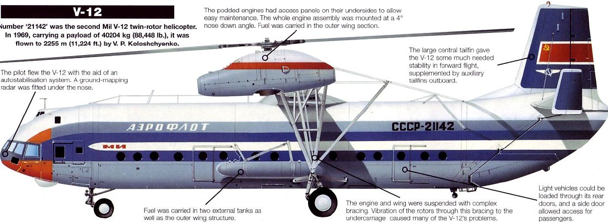
The Mil V-12 (Mi-12), which was allotted the NATO reporting name Homer, is currently the world’s largest helicopter, but does not appear to have progressed past the development phase. This is presumably because of technical problems rather than performance deficiencies, for the V-12 holds many world records for payload and payload- to-altitude.
The origins of the V-12 lie with a 1965 Soviet air force requirement for a heavy-lift helicopter able to carry major missile components. These would be brought into remote missile site areas by fixed-wing aircraft, notably the Antonov An-22, and then lifted from the airfield to the launch site by the new helicopter.
There also existed a civil requirement for such a machine, principally for use in developing Siberia which is resources-rich but communications-poor. The military specification, calling for a tandem-rotor configuration using dynamic system components from existing helicopters, was paramount, however, as evidenced by the fact that the V-12 has the same basic hold dimensions as the An-22: 4.4m by 4.4m, with length only 4.85m less than that of the An-22 at 28.15m.
Although the requirement called for a tandem-rotor layout, Mil received early permission to concentrate instead on a twin side-by-side rotor configuration, which the design bureau claimed as having better reliability, fatigue life and stability. Thus the V-12, which first flew in the second half of 1968, appeared with a fuselage resembling that of a fixed-wing aircraft, from whose top spring two inversely tapered wings carrying the twin dynamic systems at their tips. Each of these dynamic systems is very closely related to that of the Mi-6 helicopter: it comprises two 6500shp Soloviev D- 25VF turboshafts, uprated from the 5500shp of the Mi-6’s Soloviev D-25V by the addition of a zero stage to the compressor and by an increase of operating temperature.
The two engines are located side-by-side with twin intakes, and drive five-bladed metal rotors. The left rotor rotates anti-clockwise and the right unit clockwise; the two units are connected by transverse shafting to ensure synchronization and the continued rotation of both units in the event of engine failure at either wingtip. The lower part of each cowling can be dropped to form a working platform for mechanics. Fuel is housed in two cylindrical tanks mounted externally on the lower fuselage sides. The main units of the fixed tricycle undercarriage are supported by a plethora of struts bracing the wings and running from the lower fuselage, wings and engines.
Although the V-12 could accommodate large numbers of passengers, tip-up seats are provided for only 50; the reason for this is that the type is intended mainly for heavy-lift work, with accommodation only for drilling crews, missile crews etc. The main freight hold has overhead rails for a moving crane which has four loading points, each rated at 2500kg, or can alternatively lift a single item of up to 10000kg. The bottom of the rear fuselage comprises an inbuilt loading ramp, with large clamshell doors forming the rear fuselage aft of this point.
The first prototype crashed, apparently as a result of engine failure, during 1969, but the second prototype established seven world records the same year. On February 22, the V-12 lifted a payload of 31,030kg to 2951m, breaking the records for maximum payload carried to 2000m. On August 6, a load of 40,204.5kg was lifted to an altitude of 2255m, which constituted a new payload record for 2000m, and payload-to-height records for 35,000kg and 40,000kg.
Now, let’s look at the Hiller X-18 designed by a team of engineers which Burt Rutan was a part.
Hiller X-18
(1959)

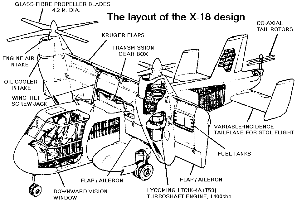
Hiller Aircraft was one of the pioneers in VTOL flight and investigated the possibilities of the phenomena following World War II. Its investigations pointed to the advantages to be derived from the Tilt-Wing concept. It generated enough interest from the Navy with its expertise, and received a contract in 1957 for a four-ton payload, tilt-wing transport.
The company’s potential also attracted the interest of the Air Force in 1954. Three years later the Air Force pushed for the construction of a prototype and a flight test program, and awarded the company a $4 million contract to accomplish the awesome task. Even though the plane was built from scratch as a research-gaining test bed the X-18 definitely carried the look of an era transport and it would also be the largest VTOL aircraft built to date at the time.
The contract called for a twin-engine Tilt-Wing convertiplane, was also required to have a significant forward speed capability of about 640km/h in addition to its vertical take-off and landing capabilities,
Another consideration of the flexibility of the plane was that where landing strips were available the X-18 could be used in a conventional take-off mode resulting in an increased payload capability. The model was to also be constructed using as much conventional fabrication techniques as possible. The task was aided greatly during its early phases by a series of wind tunnel tests at NACA Langley, Virginia. The first, and only, prototype was completed in 1958 and quickly became involved in an extensive ground test program.
The first actual flight test took place on November 24, 1959. There would be twenty flights in the program with the program ending in July 1961. It was that final flight of the program that actually spelled disaster.
When a problem occurred with one propeller’s pitch control system the program was terminated; however, the fact that the engines were not cross-shafted together contributed to the termination as well.
But after the flight testing was over there was still another important mission to be performed by the X-18. During this phase the plane would serve to generate a data base for the four-engine XC-142 Tilt-Wing transport that would follow.
During its final days, the X-18 would be damaged when a ground test stand, upon which it was mounted, failed. Shortly thereafter, the X-18, like a number of the other X planes, would be disassembled and cut up for scrap.
Looking at the engineering of the X-18 it quickly comes to light that this was an extremely complicated machine, and certainly pushed the state-of-the-art for the time period.
The propulsion system, although it wasn’t immediately evident when viewing the plane, carried three engines. Besides the obvious pair of Allison T40-A-14 turboprops, each mounting a pair of Curtiss-Wright turbo-electric three-bladed propellers and putting out a total of just over 11000 horsepower, there was also a 1530-kg-thrust Westinghouse J-34 turbojet located in the aft fuselage that provided the greatly-needed pitch control. It was located in the aft fuselage. The T40, by the way, was the same engine that was used in the Convair XFY-1 “Pogo” Tail Sitter VTOL fighter.
The thrust from this auxiliary engine was diverted through a pipe that protruded out the rear of the aircraft and terminated with an up-and-down diverter valve. By applying the thrust in either an up-or-down direction, the devise was able to maintain the craft’s pitch control.
The T-40 props were huge, 4.8m in diameter, with the props geared to be counter-rotating. The engines provided significant lift, thrust, providing the X-18 with excellent performance through transition from vertical to horizontal flight. Following transition to its forward velocity the X-18 acquired the look of a conventional transport, and it was hard to even identify its VTOL capability.
The cockpit featured a standard cockpit layout, but stability augmentation was built into the roll and pitch axes. Hydraulic boost was used on the ailerons, and a jet diverter and a servo tab boost on the rudder. The only additional control on the cockpit panel was a lever to tilt the wing, which was mechanically locked in the full-down position, but hydraulically locked when in the intermediate positions.
Have a good weekend, fly safe/be safe, and enjoy time with family and friends.
Robert Novell
December 6, 2019


